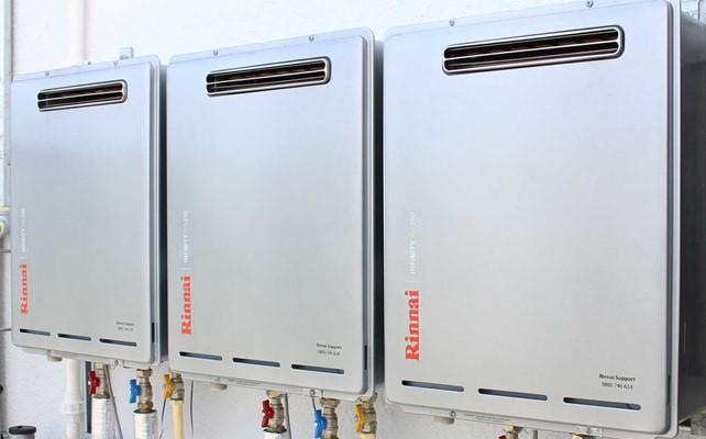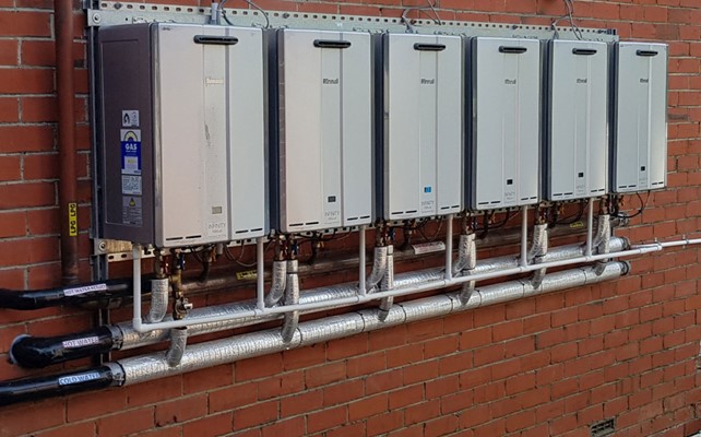
Ring mains (or circulatory heated water reticulation) are a great way to ensure your customers get near-instant hot water at the tap. At Rinnai, we see many successfully implemented ring-main projects. Unfortunately, we also see a number that don’t operate as well as the customer would like.
Ring mains can be divided into two basic types: temperature-controlled and tank temperature.
Temperature-controlled ring mains are normally below 55°C in residential buildings to meet the safe water temperature limits of G12/AS1 of the Building Code. They may also be controlled below 45°C for retirement homes (and other buildings defined by G12/AS1 6.14.1 b), or greater than 60°C. The reasons for this may include that tank temperatures are higher than the pipe system rating, there is a poorly controlled temperature source, or the hydraulic designer prefers to have a known temperature circulating.
Insulating ring mains to a very high standard is essential. Any ring main is a fixed operating cost for a building. Where occupancy is low (for example, hotels during the pandemic), the heat loss from the ring main can be a significant proportion of the hot water energy use. Remember, in systems not incorporating UV sterilisers, return water temperature must be greater than 55°C (AS/NZS3500.4) or 60°C (G12/AS1).
For applications where temperature is limited to 45°C, an even higher standard of insulation is required to ensure water at the last fixture is sufficiently hot.
Temperature gauges should be fitted to the storage vessel (or heat source) outlet, return water connection, and after the mixing valve of temperature-controlled systems. It is important that the sensing elements of gauges are inserted into pockets which sit well into the flow stream of a pipe. We have seen many temperature gauges which do not sense the actual water flow temperatures. This makes it difficult to demonstrate compliance.
Tank Temperature Systems
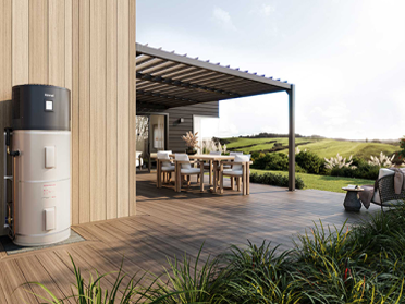
Tank temperature systems have the advantage of simplicity. They require lower costs to install where there are a small number of outlets. Water can be tempered to different temperatures at different fixtures.
Challenges with tank temperature systems include: excess temperature degrading the polymer pipe; access to point of use mixing valves for maintenance; sticking non-return valves causing cross-connection through mixing valves (which results in low temperature water and high running costs); cost of valves in large installations.
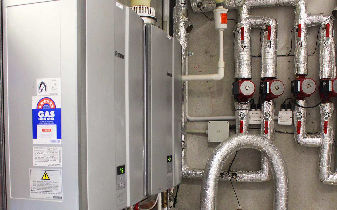
Temperature-Controlled Systems
These are commonly set to 55°C in medium to large accommodation buildings which allows simpler connections to each unit without mixing valves. The possibility of future cross-connections through partially open non-return valves is eliminated.
The most common issue found with installation of mixing valves in temperature-controlled systems is the failure to include a short circuit path from the ring main return to the cold port of the mixing valve (see Figure 1). This is required to supply the mixing valve with a source of water at a temperature below the set temperature at times of no draw. Without this connection supplying the cold port, the mixing valve will have flow only into the hot connection which will then close to limit the temperature. This results in no flow in the ring main causing several issues: the ring main will cool off; the circulating pump will have its economic life reduced by pumping against a static head for long periods; the mixing valve will be damaged over time as it blocks the hot port against the pump pressure. All valve manufacturers will show the required hydraulic arrangements as part of their installation manuals.
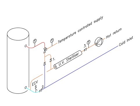
Figure 1. Temperature-controlled ring main: 1. Return connection to mixing valve; 2. Cold connection to mixing valve; 3. Ring main return non-return.
The next most common issue with mixing valve installations is connecting the cold port of the valve on the tank side of an expansion control valve. This can result in only high temperature water being available to the cold side of the valve for periods of operation. It is best to ensure “virgin” cold water is available to the cold side of the mixing valve with the use of a non-return valve (see Figure 1.). Remember that an effective non-return valve is also required on the return connection.
Multiple Mixing Valves in Temperature-Controlled Systems
It is important to ensure these are hydraulically balanced very accurately. Do not attempt to use different sizes or models of valves in parallel. The circulating pump must be capable of ensuring equal flow through all valves to meet the manufacturers minimum specification. This ensures the sensing elements can correctly position the valves at all times.
UV Sterilisers
In any ring main system with a return temperature lower than 55°C, a UV sterilizer must be used to disinfect legionella bacteria. The disadvantage with this is the requirement to replace bulbs every year – at least. The site needs some means of monitoring the status of the bulb whether via an alarm or regular documented checks. It is important to use only reputable well-supported brands to ensure replacement bulbs will continue to be available.
Issues with UV sterilisers include: failed bulbs, products intended for cold water only used in hot water applications, and products without appropriate IP ratings installed outdoors.
Ring mains implemented well result in highly satisfied customers. The Rinnai Commercial Hot Water team are available to assist in specifying to ensure Rinnai products work well in these applications. We also peer review hydraulic designs to confirm no obvious issues exist.
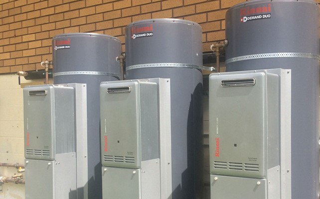
Multiple Loop Systems
There are two main ways of arranging multiple loop systems:
The first way is to use thermal balancing valves on all but the longest/most flow-resistant loop. The advantage of thermal balancing valves is that a relatively small circulating pump(s) can be used. Ensuring the longest loop is not controlled is important to keep water flowing across the temperature mixing valve and ensure the pump is not damaged by pumping against a static head. It is important to remember larger multi-stage pumps will have a minimum flow rate. Dropping below this flow rate will result in premature pump failure. We have seen large pumps installed with thermal balancing valves with the valve on the shortest loop knocking as pressure was relieved through the closed valve.
The second method is to use flow restrictors on each loop and a circulating pump large enough to meet the flow in each loop x number of loops.
The important thing is not to mix and match the two concepts. Symbols used on hydraulic drawings can be confusing so it is important to understand the hydraulic engineers’ design concept.